- Design a machine that includes mechanism + actuation + automation + application. - Build the mechanical parts and operate it manually. - Document the Group Project.
*Individual Assignment
- Document your individual contribution.
Machine Design (part 2 of 2)
* Group Assignment (refer to our Group Page)
- Actuate and automate your machine. - Document the group project.
*Individual Assignment
- Document your individual contribution.
checklist
☑ Documented the machine building process to the group page. ☑ Documented your individual contribution to this project on your own website. ☑ Linked to the group page from your individual page as well as from group page to your individual pages. ☑ Shown how your team planned, allocated tasks and executed the project (Group page). ☑ Described problems and how the team solved them (Group page). ☑ Listed possible improvements for this project (Group page). ☑ Included your design files (Group page). ☑ You need to present your machine globally and/or include a 1 min video (1920x1080 HTML5 MP4) + slide (1920x1080 PNG) (Group page).
Individual Contribution
Machine Component
My Contribution
Coin Feeder
Designed, 3D printed and tested the coin feeder mechanism.
Researched and wrote the program to control the stepper motor.
Integrated the stepper motor to the coin sorter machine to automate it.
Coin-Sorting gates
Integrated the coin-sorting gate to the coin feeder.
Pegboard Frame
Helped to apply acrylic glue to strengthen frame.
Housing for SEEED Xiao RP2040 board
Designed, 3D printed and tested the SEEED Xiao RP2040 board housing.
Documentation
Supported documentation as Group member.
Coin Feeder
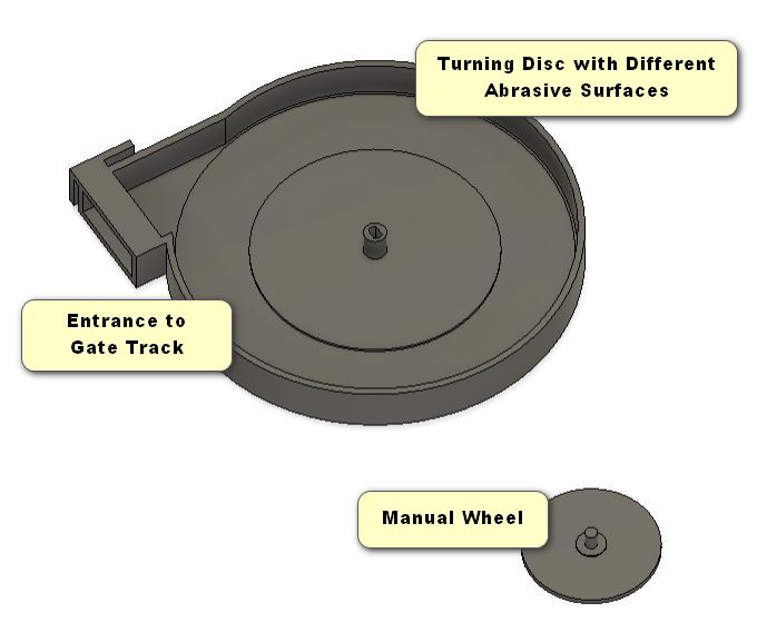
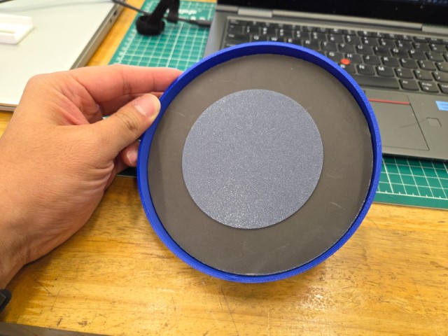
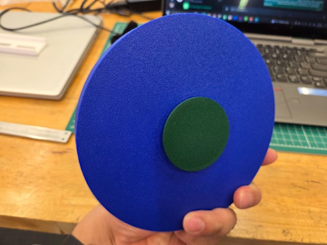
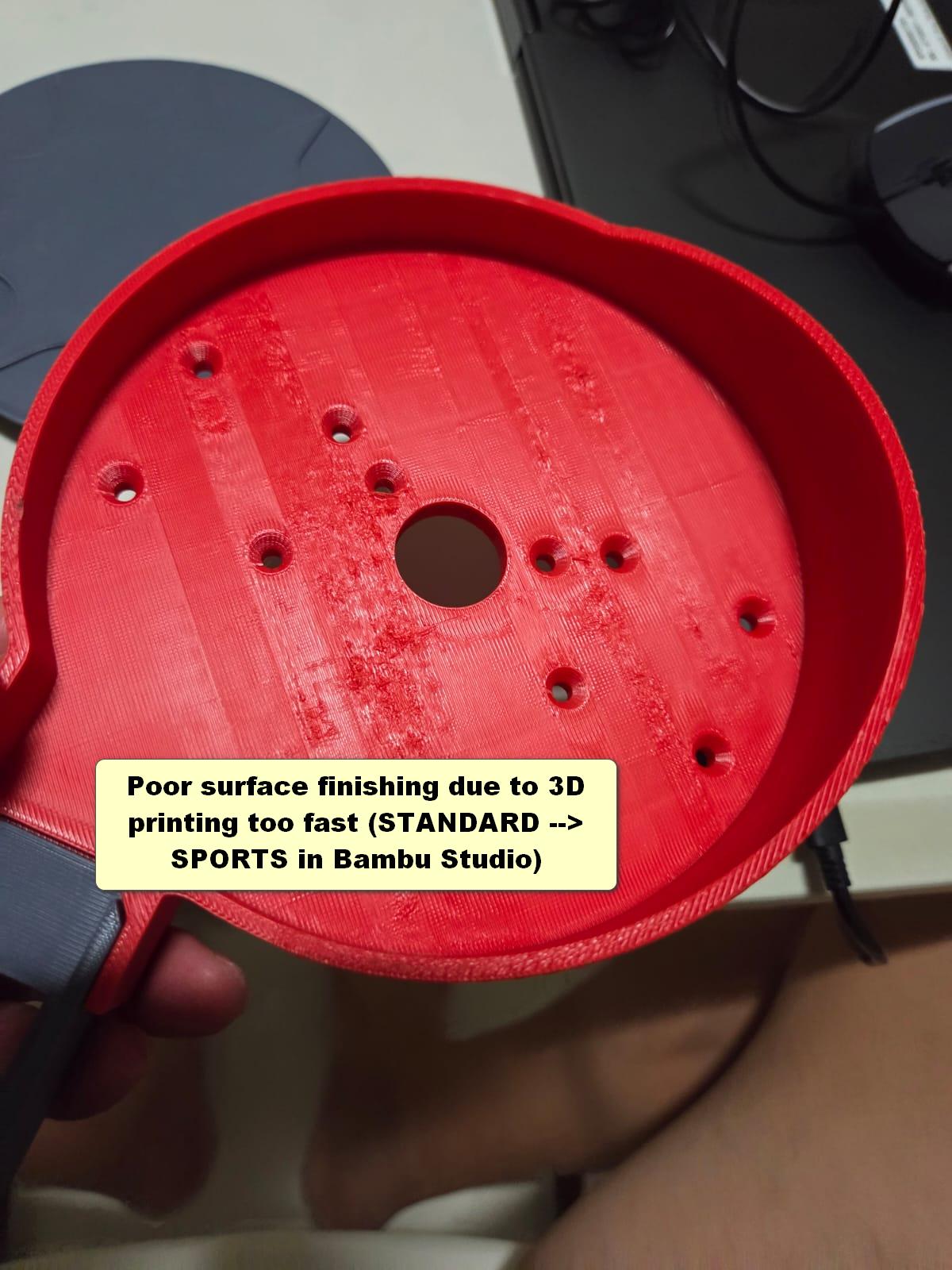
This was my main contribution during this week’s machine-building task. I had to come up with a solution that was both effective and simple to build, as we were tight on time due to remaining assignments, feedback from both local and global evaluators, and our own final projects. The first photo above shows our initial coin feeder design, which relied on friction to move coins upward along a rotating disc and drop them into the gate track. The third photo displays the rear view of the feeder, designed for manual operation. Despite testing with three different abrasive surfaces — original rough print, fine sandpaper, and coarse sandpaper — all attempts were unsuccessful, as the coins consistently failed to ascend as intended. Two scenarios were observed: 1) Greater inclined angle – While the disc could turn more easily due to reduced weight load, the coins failed to climb because gravity outweighed the frictional force. 2) Smaller inclined angle – Coins could climb more easily, but the increased weight from the coins made the disc harder to rotate.
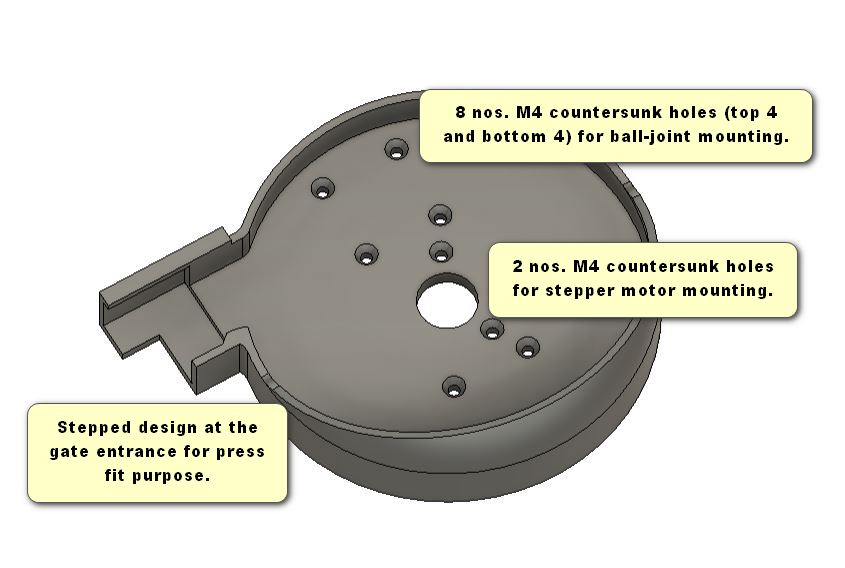
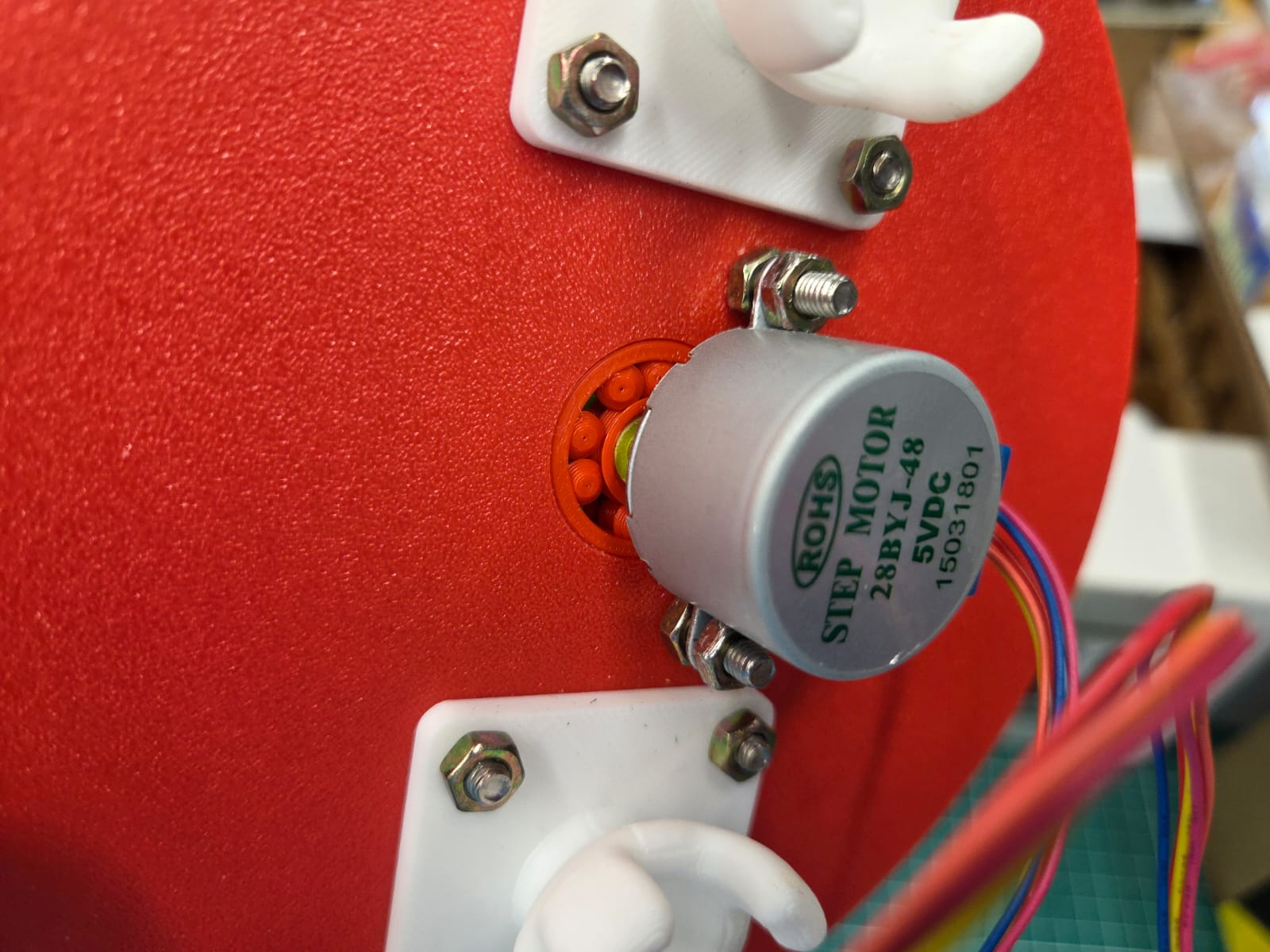
Given these issues, we quickly decided to modify our approach by adding a separator to the disc. This adjustment resolved both the friction problem and the difficulty with disc rotation. Below are photos of the revised 3D-printed components used in the coin feeder:
After confirming the new design worked manually, we moved on to automating the process using a stepper motor. Our instructor, Mr. Steven Chew, shared guidance on how to run a BYJ48 stepper motor using code. Initially, I struggled with setting up a basic working program — even when referencing Mr. Steven Chew’s example. So, I turned to one of my students, Lokesh (an EEE student skilled in programming), for help.
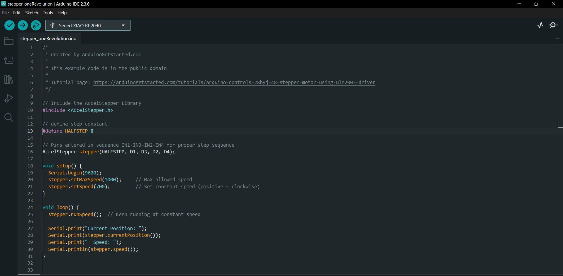
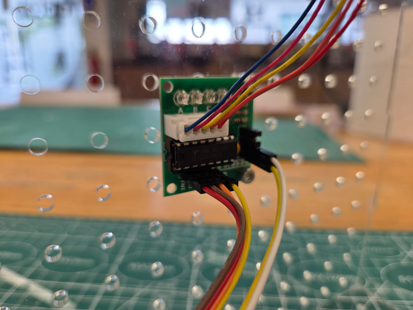
We started with the Arduino IDE example code Stepper --> stepper_oneRevolution. Along the way, we encountered several issues: 1. Incorrect wiring. 2. Recommended switching to half-step mode instead of full-step. 3. Reducing motor speed. 4. Ensuring stable power supply. 5. Simplifying the code by removing acceleration logic. 6. Ensuring continuous rotation. Code below allowed us to drive the stepper motor at a consistent speed.
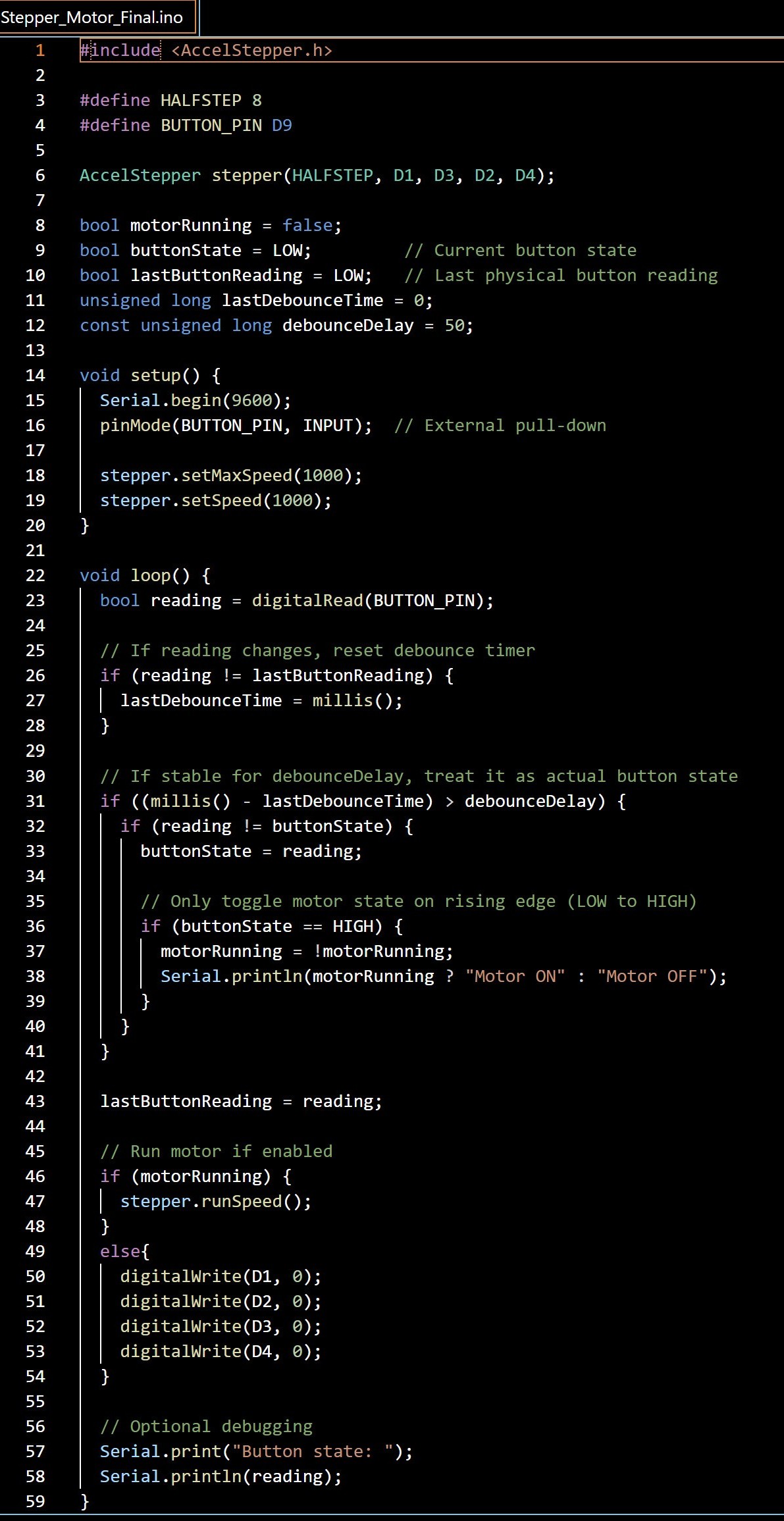
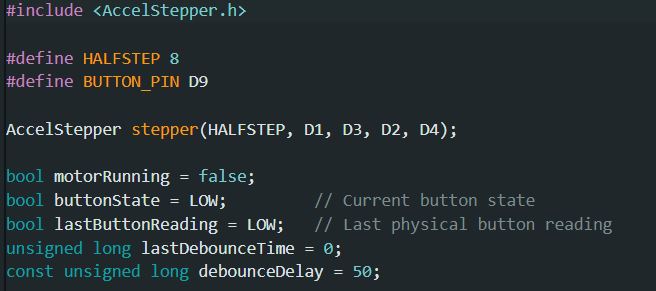
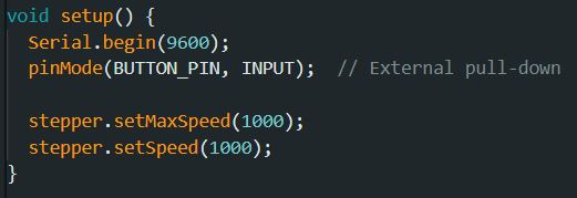
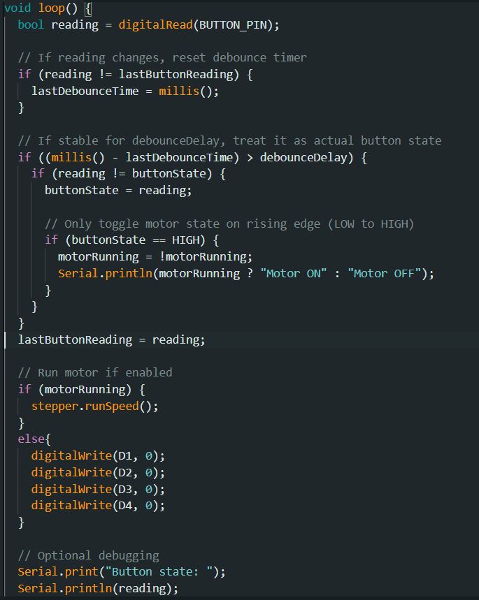
After successfully running the motor at a constant speed, I implemented an input toggle using the onboard pushbutton on my SEEED Xiao RP2040 PCB. The button uses an internal pull-down resistor to control the stepper motor on/off. Some explanation on the program above: 1) This code sets up a stepper motor using the AccelStepper library in half-step mode and assigns control to pins D1 through D4. It also defines a pushbutton on pin D9 to toggle the motor on and off. To ensure reliable button presses, the code includes a debounce mechanism that waits 50 milliseconds after detecting a change in button state before acting on it. Variables are initialized to track the motor state and manage button input logic, preparing the system for clean toggling behaviour during operation. 2) This setup function initializes serial communication at 9600 baud, configures the button pin (D9) as an input with an external pull-down resistor, and sets the stepper motor's maximum and operating speed to 1000 steps per second using the AccelStepper library. 3) This loop() function checks the state of a pushbutton using debouncing logic to ensure reliable input detection. When a stable button press (LOW to HIGH transition) is detected, it toggles the motorRunning state. If the motor is enabled, it runs the stepper motor at a constant speed using the stepper.runSpeed() function. If the motor is off, it disables all four motor control pins. The function also prints the button state and motor status to the serial monitor for debugging. Video below shows the turning of the stepper motor to drive the separator.
Coin-Sorting gates
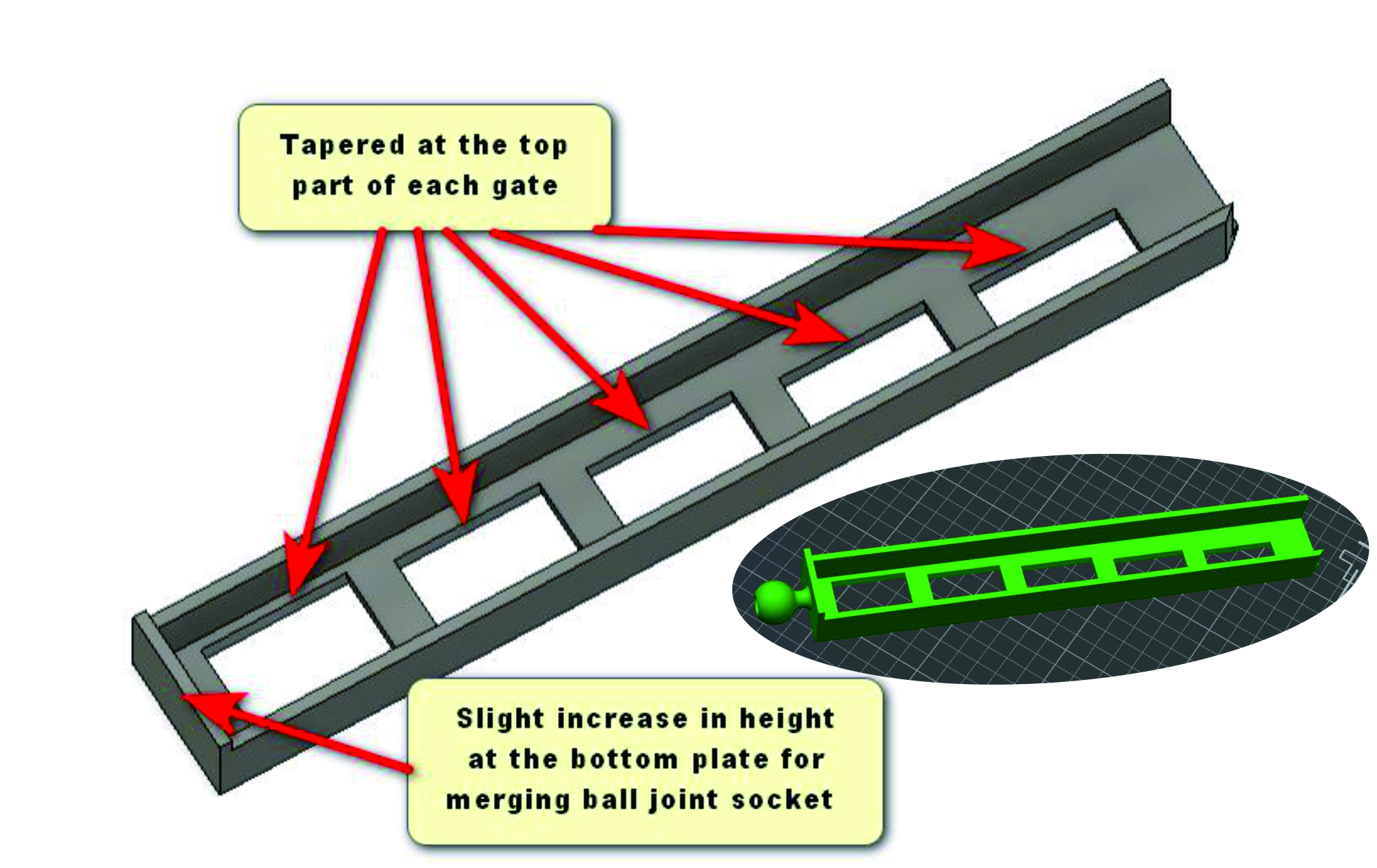
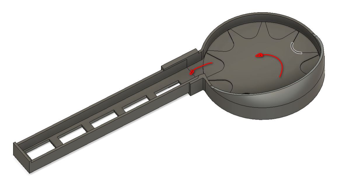
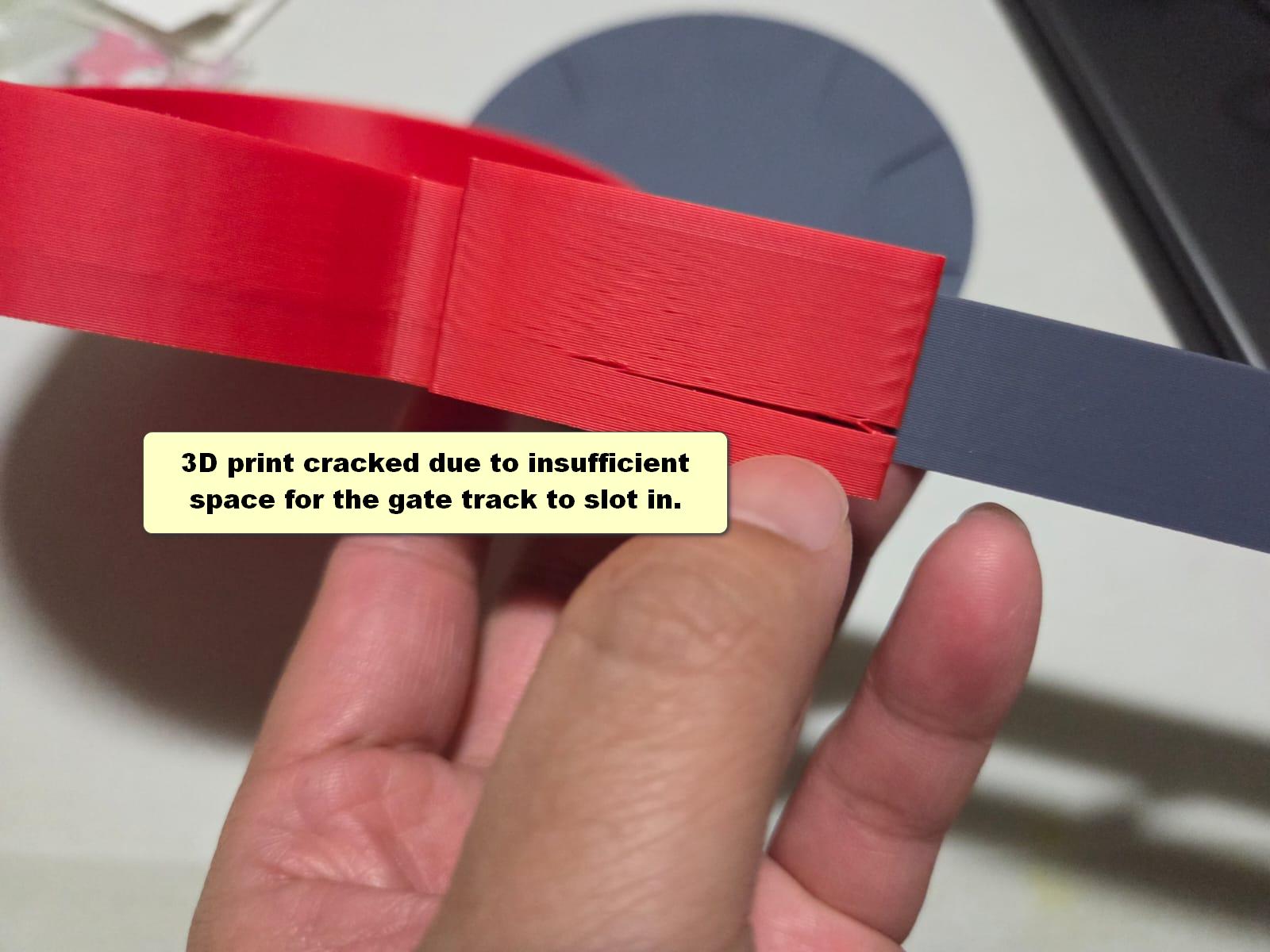
After my Fab Academy partner, Florimond Chu, designed the gates, I used his file and integrated it with the coin feeder via a press-fit connection to ensure a smooth transition for the coins. I also added a small tapered section above each gate so the coins fall more easily into their respective containers. Here is the final assembly of coin feeder and gate track: After a few tries on the tolerance, I finally got the correct print files to assemble the parts with press-fit tolerance. Photos below shows the wrong design and setting of the 3D-printed files:
Pegboard Frame
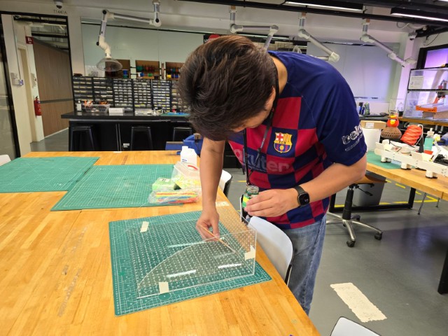
For this task, I handled the acrylic gluing process. Since Florimond had never done this before, I guided him through the proper glue application techniques during panel assembly.
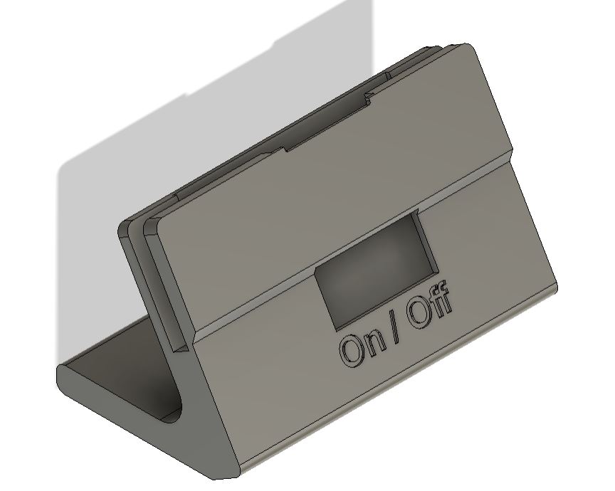
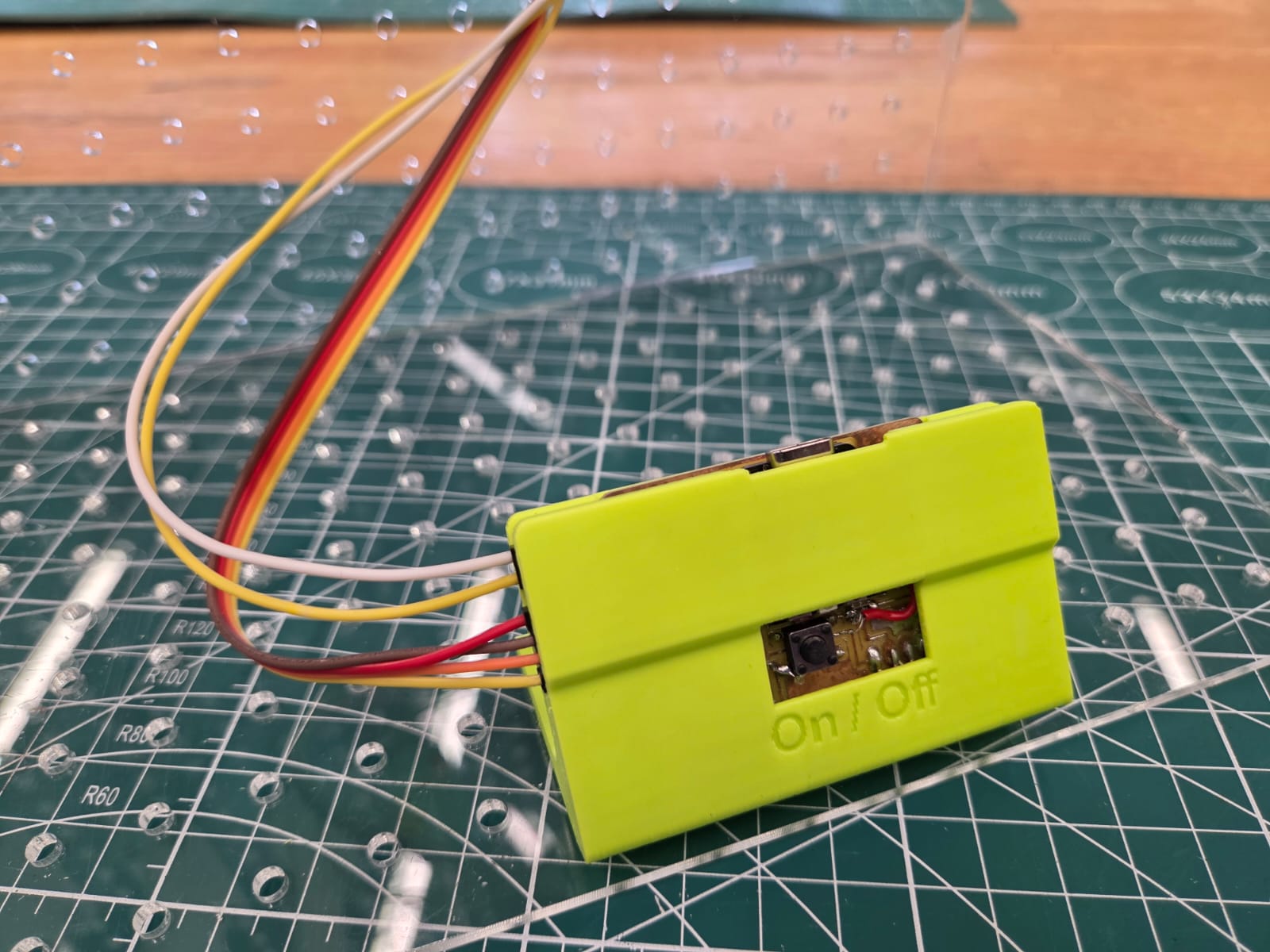
Housing for Xiao RP2040 board
Once the stepper motor setup was confirmed, the next step was mounting the electronics. Besides the motor (mounted under the feeder), we had two additional components: • The stepper motor driver board. • The SEEED Xiao RP2040 PCB. I mounted the motor driver directly onto the pegboard with M3 x 20mm screws. For the PCB, I 3D-printed a custom housing that exposes only the pushbutton for operation.
Reflection
Even though we finalized the design well before the building week, we faced significant challenges during implementation. The two main difficulties were: 1. Designing an effective coin-feeding mechanism. 2. Determining the optimal tilt angle for the sorter. Big thanks to my teammate, Florimond Chu, whose experience-driven ideas greatly contributed to the success of our project. Together, we created a simple yet functional machine that can inspire students by showing the full journey from idea to working prototype.